Shop
Showing 1–9 of 14 results
-
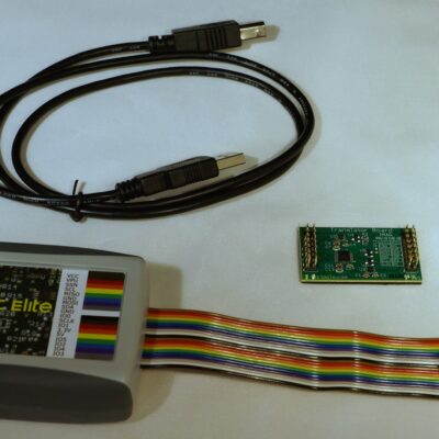
USB to I2C Elite Package
$399.00The USB to I2C provides bi-directional communication with I²C devices using the I²C protocol. You should be experienced with the I²C Bus protocol before using this product.
USB-to-I2C Elite Package includes:
- Elite hardware
- I2C, SPI, and GPIO Translator/Level Shifter
- Downloadable software
- 18 pin cable
- 3 ft. USB cable
Savings of $29.00
-
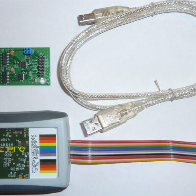
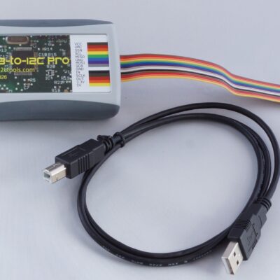
USB to I2C Professional Package
$319.00USB-to-I2C Adapter Professional Package includes:
- Pro hardware
- I2C, SPI, and GPIO Translator/Level Shifter
- Downloadable software
- Ribbon cable
- 3 ft. USB cable
Savings of $29.00
-
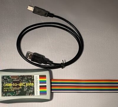
USB to I2C Elite
$329.00USB-to-I2C Elite is a general purpose I2C and SPI interface tool that allows a user to communicate with any I2C or SPI slave devices.
-
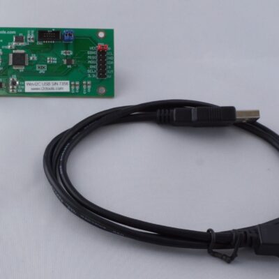
USB to I2C Professional no enclosure
$249.00USB-to-I2C Professional is a general purpose I2C and SPI interface tool that allows a user to communicate with any I2C or SPI slave devices.
-
USB to I2C Professional with enclosure
$269.00USB-to-I2C Professional is a general purpose I2C and SPI interface tool that allows a user to communicate with any I2C or SPI slave devices.
-
Win-I2CUSBDLL
$249.00Win-I2CUSBDLL is a general purpose I2C and SPI tool that allows a user to communicate with any I2C or SPI slave device.
-
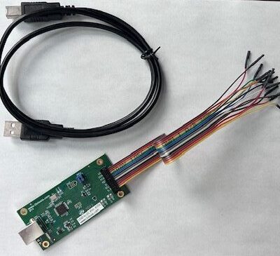
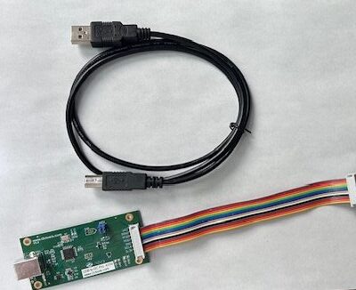
USB to I2C Professional with 14 pin split cable
$279.00USB-to-I2C Professional with 14-pin split cable includes:
- Hardware
- Downloadable software
- 14-Pin split cable
- 3 ft. USB cable
-
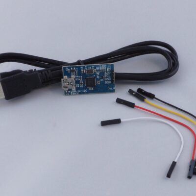
USB to I2C Basic
$129.00USB-to-I2C Basic is an interface tool that is a compact, yet powerful general-purpose I2C tool that allows a user to communicate with any I2C slave device. Standard, fast mode, and Fm+ (fast mode plus) is supported.
The USB to I2C interface connects to a standard USB port found on all Personal Computers and provides bi-directional communication with I²C devices using the I²C protocol. The hardware is powered directly from the PC’s USB port, and there’s no need to install device drivers since it uses standard USB HID drivers already installed in Windows. This will allow you to get started quickly with the intuitive and flexible software that it included with USB-to-I2C Basic.
-
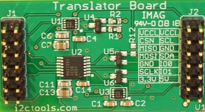
Translator/Level Shifter
$99.00The I2C, SPI, and GPIO Translator/Level Shifter incorporates high-speed digital level shifters to extend the lower operating voltage range of the USB-to-I2C products.